Hifimediy i2S DAC, I2S and left justified input, ES9023, 192KHz/24bit
USD18.99
Out of stock
Notify me when this product is in stock
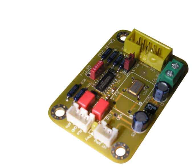
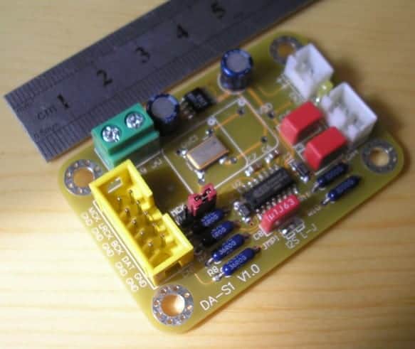
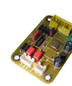
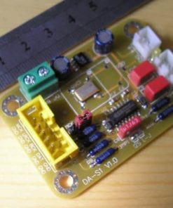
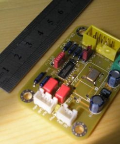
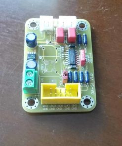
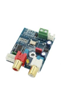
Here is our original ES9023 DAC with I2S input. LT1763 ultra low noise regulator and switchable on board (asynchronous) or external master clock. 40MHz on board oscillator installed.
Oscillator of minimum 128 times sample rate can be used, max 100MHz. 40MHz is required for 192KHz sample rates-
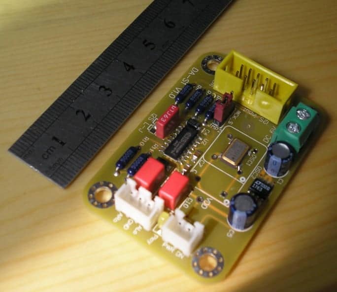
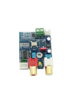
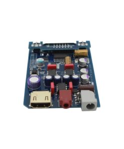
It comes fully assembled just as pictured.
Power requirement: 6VDC. 4-12VDC is ok., minimum 50mA.
CN3 (the two pin white connector) is a power down selector. Can be controlled by a switch or a open drain signal. Open = power on.
Chose external/on board MCLK (master clock) source with JMP2. Set it left towards I2S selector for external MCLK, and right towards oscillator for on board MCLK (asynchronous operation).
LT1763 LDO regulartor is set to output 3.6V to maximize the output level.
A cable that connects to the 3 and 2 pin connectors are included. I2S cable is not included.
| Weight | 0.05000000 kg |
|---|
3 reviews for Hifimediy i2S DAC, I2S and left justified input, ES9023, 192KHz/24bit
Add a review Cancel reply
Related products
Sale!
Rated 4.70 out of 5
Rated 5 out of 5
USD89.00
DACs
Rated 4.25 out of 5
USD119.00
Rated 5.00 out of 5
USD119.00
Rated 4.00 out of 5
USD18.99
DACs
Rated 5.00 out of 5
USD99.00
Sale!



David –
GGrte any pointers on the RPi with this? I am looking to add a DAC and this one looks like a winner.
GGrte –
Excellent board, I recommend it with Raspberry Pi it’s perfect ! Even with B+ version, really better.
Simon –
Hi,
Just wated to say I recieved my board but there is no online started .pdf manual or schematic online for this board.
Main thing is would like to know how to connect to the board for example ? A mini spdif module ? or 9V Rechargerble Battery
This is my first project so bit tricky :0