Amplifier manual for Tripath amplifiers (T1, T1-M, T2, T3, T3S, T4)
This is a manual covering all the hifimediy Tripath based amps (T1, T1-M, T2, T3, T3S, T4).
General
First, thanks for buying the Hifimediy amp! All these amps are using the Tripath TK2050 chipset, that is the tc2000 controller and the output chips (differ depending on model).
All the output chips are similar, but have different voltage range and might sound a little different.
The T1 uses 1 x sta508 or sta510a
T1-M has 1 x sta505 sta508 (since 2015)
T2 has 2 x sta505 sta508 (since 2015)
T3 has 2 x sta517b sta516 since 2015
T4 has 1 x sta517b sta516 since 2015
Gain for T1, T1-M, T2 amps are 15x.
Gain for T3 mono, T3S, T4 amps are 25x.
The TK2050 chipset features great audiophile quality sound at a very low cost because of this simple design and few parts needed.
The amps can drive speakers from 4ohm and up. Loads below 4 ohm can damage the amps. higher ohm loads are ok, we use them with 40ohm headphones, but will generate less W output.
The amps with 1 output chip for each channel (paralleled configuration) T2, T3, T3S, are better at lower impedances because of the bigger amount of current needed to be transported. The amps with half a output chip /channel (full bridged non-paralleled configuration) are good at 8ohm. They are limited at lower impedances by the high current demand.
Amplifier overview

Setting up the amp
Input signal
There is a 2.54mm connector for Left Right channel and GND.. A cable with the male connector in one end and three leads in the other end is included with all amps. You will normally solder this connector to you RCA plugs, to your input selector switch or in some cases directly to your source.
The cable currently supplied are 20cm long.

Connect RCA plugs like this:

Power connection
T1/T1-M – DC only.
T2/T3/T3S/T4 AC and DC.
For T2: It doesn’t matter where you connect DC+ and DC-
T3:
T3S/T4:If you use AC connect it like this: AC1 GND AC2. For DC a single DC+ and – is sufficient. You can also use a dual DC supply if it is stable. Wire DC as in this image. It will not damaged the amp if you connect it wrong, but it will not turn on.

Speaker connection
It should be pretty straight forward. Just one warning: Never connect L- and R- together ! They are not common GND. This would damaged the amp.
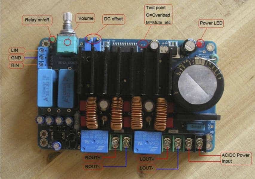
LED indicators
There are two LED indicators. The red light means that there is power connected, the green light means that the relays have turned on and the amp is functional. Normally both lights should come on. If the green light does not come one, either the voltage is too low or a technical problem has occurred. There are two LED indicators. The red light means that there is power connected, the green light means that the relays have turned on and the amp is functional. Normally both lights should come on. If the green light does not come one, either the voltage is too low or a technical problem has occurred.
DC Offset adjustors
There are two potmeters for DC offset voltage adjustment (DC voltage across speaker terminals). These are already adjusted at the factory, and should not require additional adjustment. You can measure the DC mV between Rout+ and Rout- , and then between Lout+ and Lout- to see the DC offset voltage. Normal range is 0 – 10mV

Dimension Drawings:
T1/T2:

T4 (old version)
